99 Results
View results:
Sort by:

This article presents the basic concepts in structural dynamics and their role in the seismic design of structures. Great emphasis is given to explaining the technical aspects in an understandable way, so that readers without deep technical knowledge can gain an insight into the subject.

Using the Timber Design add-on, timber column design is possible according to the 2018 NDS standard ASD method. Accurately calculating timber member compressive capacity and adjustment factors is important for safety considerations and design. The following article will verify the maximum critical buckling strength calculated by the Timber Design add-on using step-by-step analytical equations as per the NDS 2018 standard including the compressive adjustment factors, adjusted compressive design value, and final design ratio.

The National Building Code of Canada (NBC) 2020 Article 4.1.8.7 provides a clear procedure for earthquake methods of analysis. The more advanced method, the Dynamic Analysis Procedure in Article 4.1.8.12, should be used for all structure types except those that meet the criteria set forth in 4.1.8.7. The more simplistic method, the Equivalent Static Force Procedure (ESFP) in Article 4.1.8.11, can be used for all other structures.

Wind direction plays a crucial role in shaping the outcomes of Computational Fluid Dynamics (CFD) simulations and the structural design of buildings and infrastructures. It is a determining factor in assessing how wind forces interact with structures, influencing the distribution of wind pressures, and consequently, the structural responses. Understanding the impact of wind direction is essential for developing designs that can withstand varying wind forces, ensuring the safety and durability of structures. Simplified, the wind direction helps in fine-tuning CFD simulations and guiding structural design principles for optimal performance and resilience against wind-induced effects.

The response spectrum analysis is one of the most frequently used design methods in the case of earthquakes. This method has many advantages. The most important is the simplification: It simplifies the complexity of earthquakes so far that the design can be performed with reasonable effort. The disadvantage of this method is that a lot of information is lost due to this simplification. One way to moderate this disadvantage is to use the equivalent linear combination when combining the modal responses. This article explains this option by describing an example.

The modal relevance factor is a result of the linear stability analysis and qualitatively describes the degree of participation of individual members in a specific mode shape.

For the stability verification of members using the equivalent member method, it is necessary to define effective or lateral-torsional buckling lengths in order to determine a critical load for stability failure. In this article an RFEM 6-specific function is presented, by which you can assign an eccentricity to the nodal supports and thus influence the determination of the critical bending moment considered in the stability analysis.

The Steel Joist Institute (SJI) previously developed Virtual Joist tables to estimate the section properties for Open Web Steel Joists. These Virtual Joist sections are characterized as equivalent wide-flange beams which closely approximate the joist chord area, effective moment of inertia, and weight. Virtual Joists are also available in the RFEM and RSTAB cross-section database.

This article will show you the Building Model add-on, which has been enhanced with one important advantage: calculating the center of mass and center of rigidity.

The “Modal Analysis” add-on in RFEM 6 allows you to perform modal analysis of structural systems, thus determining natural vibration values such as natural frequencies, mode shapes, modal masses, and effective modal mass factors. These results can be used for vibration design, as well as for further dynamic analyses (for example, loading by a response spectrum).

This article will show you a practical example of how to determine critical load factors and corresponding mode shapes in RFEM 6.

Given that realistic determination of the soil conditions significantly influences the quality of the structural analysis of buildings, the Geotechnical Analysis add-on is offered in RFEM 6 to determine the soil body to be analyzed.
The way to provide data obtained from field tests in the add-on and use the properties from soil samples to determine the soil massifs of interest was discussed in Knowledge Base article “Creation of the Soil Body from Soil Samples in RFEM 6”. This article, on the other hand, will discuss the procedure to calculate settlements and soil pressures for a reinforced concrete building.

The stand-alone program RSECTION is at your disposal for determining section properties and performing stress analysis for thin-walled and massive cross-sections. The program can be connected to both RFEM and RSTAB so that sections from RSECTION are also available in the RFEM and RSTAB library. Likewise, internal forces from RFEM and RSTAB can be imported into RSECTION.

You can use the stand-alone program RSECTION to determine the section properties for any thin-walled and massive cross-sections, as well as to perform a stress analysis. The previous Knowledge Base article titled "Graphical/Tabular Creation of User-defined Cross-sections in RSECTION 1" discussed the basis of defining cross-sections in the program. This article, on the other hand, is a summary of how to determine the section properties and perform a stress analysis.

Modal analysis is the starting point for the dynamic analysis of structural systems. You can use it to determine natural vibration values such as natural frequencies, mode shapes, modal masses, and effective modal mass factors. This outcome can be used for vibration design, and it can be used for further dynamic analyses (for example, loading by a response spectrum).

RSECTION 1 is a stand-alone program for determining section properties for both thin-walled and massive cross-sections, as well as for performing a stress analysis. In addition, the program can be connected to both RFEM and RSTAB: sections from RSECTION are available in the RFEM/RSTAB libraries, and internal forces from RFEM/RSTAB can be imported into RSECTION.

In accordance with Sect. 6.6.3.1.1 and Clause 10.14.1.2 of ACI 318-19 and CSA A23.3-19, respectively, RFEM effectively takes into consideration concrete member and surface stiffness reduction for various element types. Available selection types include cracked and uncracked walls, flat plates and slabs, beams, and columns. The multiplier factors available within the program are taken directly from Table 6.6.3.1.1(a) and Table 10.14.1.2.

The stability checks for the equivalent member design according to EN 1993-1-1, AISC 360, CSA S16, and other international standards require consideration of the design length (that is, the effective length of the members). In RFEM 6, it is possible to determine the effective length manually by assigning nodal supports and effective length factors or, on the other hand, by importing it from the stability analysis. Both options will be demonstrated in this article by determining the effective length of the framed column in Image 1.

The new RFEM software generation provides the option to perform stability design of tapered timber members in line with the equivalent member method. According to this method, the design can be performed if the guidelines of DIN 1052, Section E8.4.2 for variable cross-sections are met. In various technical literature, this method is also adopted for Eurocode 5. This article demonstrates how to use the equivalent member method for a tapered roof girder.

The add-on modules for designing structural member components according to national, European, and international standards also show design results in addition to numerical output in tables graphically, as diagrams displayed on the framework.

RFEM and RSTAB can calculate the critical load factor for each load case (LC) and each load combination (CO) in the case of a geometrically nonlinear calculation (second-order analysis and following).

The number of National Annexes for Eurocode 2 with regard to the design of reinforced concrete cross-sections has been extended since SHAPE-MASSIVE 6.54. Therefore, the following NAs of EN 1992-1-1:2004 + AC:2010 are available:

In RF-/STEEL EC3, sets of members are calculated according to the General Method (EN 1993-1-1, Cl. 6.3.4) together with the stability analysis. To do this, it is necessary to determine the correct support conditions for the equivalent structure with four degrees of freedom. In most 3D models today, you can quickly lose track of the location of a set of members in the system.

The RF-STABILITY add-on module determines any critical load factors, effective lengths, and eigenvectors of RFEM models. Stability analyses can be carried out by various eigenvalue methods, the advantages of which depend on the structural system as well as computer configurations.

In RF‑TENDON and RF‑TENDON Design, you can review and adjust the code‑dependent factors, calculation parameters, and calculation methods using the "Code" button. You can display the settings and adjustment options according to a chapter of a code, selecting the "Grouping" option in the dialog box.

In the case of using slow‑curing concrete (usually for thick components), you can reduce the calculated minimum reinforcement by a factor of 0.85 to apply the load due to restraint, according to EN 1992‑1‑1, Section 7.3.2. However, a precondition for reduction is that the characteristic value of the strength development r = fcm2 / fcm28 does not exceed 0.3. Other key requirements for the application of this reinforcement reduction are specified explicitly in the final planning documents.

The SHAPE‑THIN and SHAPE‑MASSIVE cross-section programs are suitable for determining the cross-section properties of common thin-walled or thick-walled sections. These cross-section properties are also available for further analyses in RSTAB and RFEM.

In RF-/FOUNDATION Pro, the user can freely select the proportion of the relieving soil pressure by means of the factor kred.

In the "Edit Load Cases and Combinations" dialog box, you can combine different load cases in one load combination under the "Load Combinations" tab.
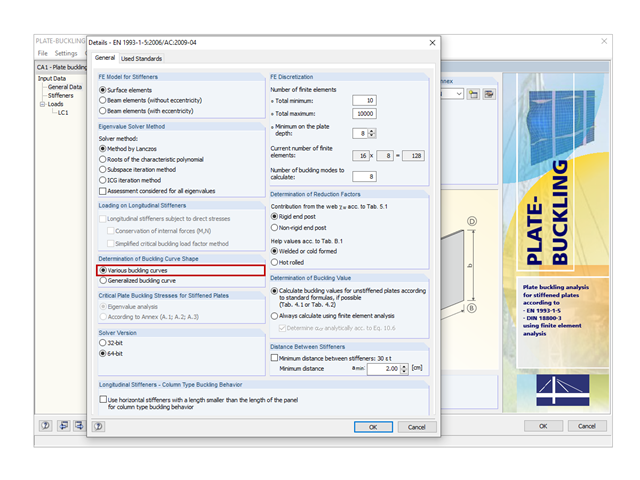
In PLATE‑BUCKLING 8, two options in the detail settings can be used to calculate the reduction factors of plate buckling.